
Systems Engineering
Systems Engineering
Establishing the Engineering Foundation of the Process
At VOLDE, systems engineering involves designing processes for raw material handling, dosing, and pneumatic conveying based on engineering principles, taking into account technical requirements and on-site conditions.
This approach aims to ensure that systems operate with predictable performance, maintain business continuity in the long term, and keep process risks under control.
_ Computational and Analytical Competence
The flow characteristics of powdered and granular materials require the simultaneous evaluation of numerous variables, such as transport velocities, pressure drops, and interactions within the system. In the systems engineering process, these variables are addressed using analytical and numerical methods.
The engineering work carried out ensures that the system operates in accordance with its capacity targets, while also enabling the proactive assessment of risks such as overloading, inefficiency, or material failure.
The main activities carried out in this context:
• Load and stress analyses
• Computational Fluid Dynamics (CFD) simulations for airflow
• Material compatibility and wear/corrosion assessments
• Sizing calculations for equipment such as motors, blowers, and valves
• System capacity and efficiency estimates

_ 3D Design and Visualization
Creating a 3D model of a system before proceeding to the production and assembly phases offers significant advantages in terms of both technical validation and on-site compatibility.
It enables a comprehensive assessment of 3D models, equipment layouts, piping routes, and service areas.
The 3D designs created serve as a common reference point during the project planning process and facilitate coordination between engineering and installation teams. This allows potential conflicts and on-site revisions to be anticipated at an earlier stage.

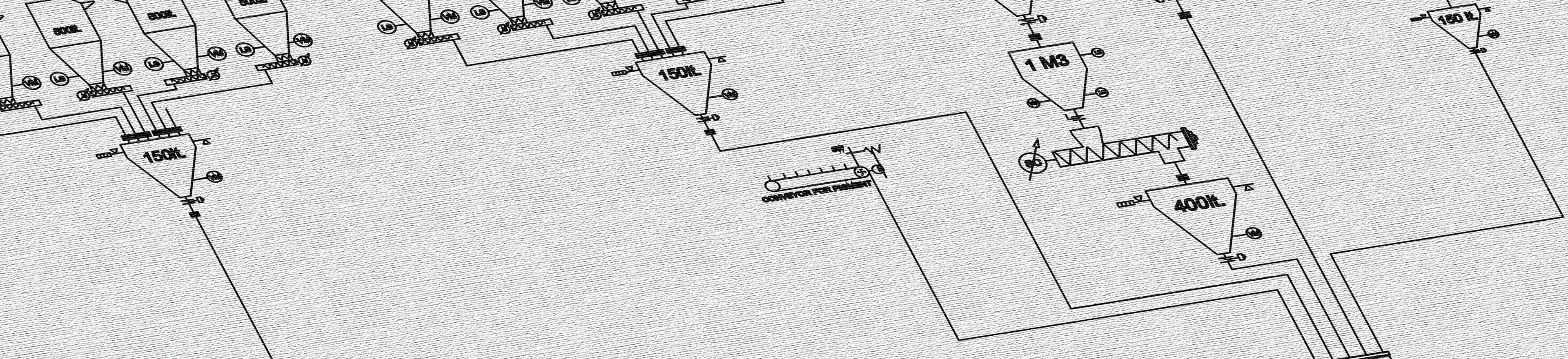
_ P&ID Design Competency
Piping and Instrumentation Diagrams (P&ID) are among the fundamental engineering documents used for the installation, operation, and maintenance of a system.
P&ID's prepared as part of systems engineering clearly and traceably define the process flow, control points, and instrumentation structure.
The diagrams are prepared in accordance with international standards and undergo quality control processes prior to commissioning. P&IDs serve as a guide during the installation phase and also serve as a reference for potential improvements or revisions during the operational phase.
Key elements covered in P&ID drawings:
• Piping layout and line connections
• Instrument layouts
• Valves and control components
• Material flow directions
• Operational data (pressure, temperature, flow rate, etc.)

Systems engineering work is not limited to theoretical designs; it is carried out with due consideration for on-site realities and operational conditions.
| Contact
Let’s understand your process and work together to implement the most accurate and reliable solution for your needs.